
Using PWM to control LED brightness
Pulse Width Modulation is a technique in which we emulate analog signals in digital pins. This tutorial we explore how to use PWM parameters to modify the operation of an LED.
Written by: Jonathan Tynan
Last updated: May 11 2025
Pulse Width Modulation (PWM) is a technique for emulating analog signals when using a digital signal source - like the pins we’ve been using. It does this by rapidly turning the digital pins on and off, effectively controlling the amount of power sent to a device. This method is widely used for controlling lights, motors and other devices. When using PWM we have several parameters we can control and modify: the PWM duty cycle, the PWM frequency and the PWM range.
PWM Frequency
Section titled “PWM Frequency”PWM operates through cycles, which are set by the frequency. The frequency of PWM indicates how many times per second the PWM signal completes one on-and-off cycle. A higher frequency means the individual cycles are completed more rapidly, which can help in smoothing the output in devices like LED’s and motors. It is measured in Hertz (Hz) and as it increases, this rapid switching becomes less and less perceptible to human senses. At low frequencies this switching is noticeable and this is seen later in this tutorial.
PWM Duty Cycle
Section titled “PWM Duty Cycle”In each of these cycles, the pin is powered high for a some part of the cycle and unpowered for the other part. We define this through the duty cycle, and this allows for fine control over the amount of power delivered to a device. In this tutorial it is shown that increasing the duty cycle of a PWM signal sent to an LED makes it appear brighter as the LED is on for more of the cycle. This value is often expressed as a percentage, for example a 50% duty cycle means that the signal is on for half of the cycle, and off for the other half.
PWM Range
Section titled “PWM Range”The range of the PWM refers to the resolution we can achieve when adjusting the duty cycle. For example, a range of 255 means that the duty cycle can be adjusted in 256 increments so that the pin could be always off (0%) or always on (100%). A larger range allows for more precise control of the output device and we explore this further in the next tutorial.
Components
Section titled “Components”Breadboard
Section titled “Breadboard”Breadboards are reusable devices used to build and test circuits. They are made up of a number of holes that are connected by hidden metal strips. Along the top and bottoms are the ground and power rails, and in the middle there are two sections separated by a channel. Each hole in a section is connected to the adjacent vertical holes. More information can be found at How to Use a Breadboard.
An LED (Light Emitting Diode) is a device that emits light when an electric current passes through it. They feature two legs, a longer positive leg (the anode) and a shorter negative leg (the cathode). The longer leg is often kinked so that both legs protrude the same distance from the LED. To use it we connect the positive lead to the GPIO pin and the negative lead to a ground pin. More information can be found at Light-Emitting Diodes (LEDs)
220 Ω Resistor
Section titled “220 Ω Resistor”The power that the Raspberry Pi can provide is actually too much for these LEDs. To prevent the LED from burning out, we must add a resistor to the circuit. The resistor limits the current that flows through the LED, preventing it from burning out. The exact value of the resistor is not critical, but too high a value does not allow enough illumination of the LED. A resistor in the range of 220 Ω to 1 kΩ should work well. More information on resistors can be found at Sparkfun - Resistors
Jumper Wires
Section titled “Jumper Wires”Jumper Wires, or DuPont wires, are used to make a temporary connection different components. They can be M/M, M/F, or F/F. We are using M/F jumper wires in this guide.
The Circuit
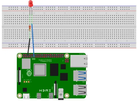
Section titled “The Circuit”Below we can see the circuit diagram for this project. Just like the blink-LED tutorial, we have the cathode of the LED connected to GPIO Pin 11, while the anode is connected to ground pin 6 through a resistor.
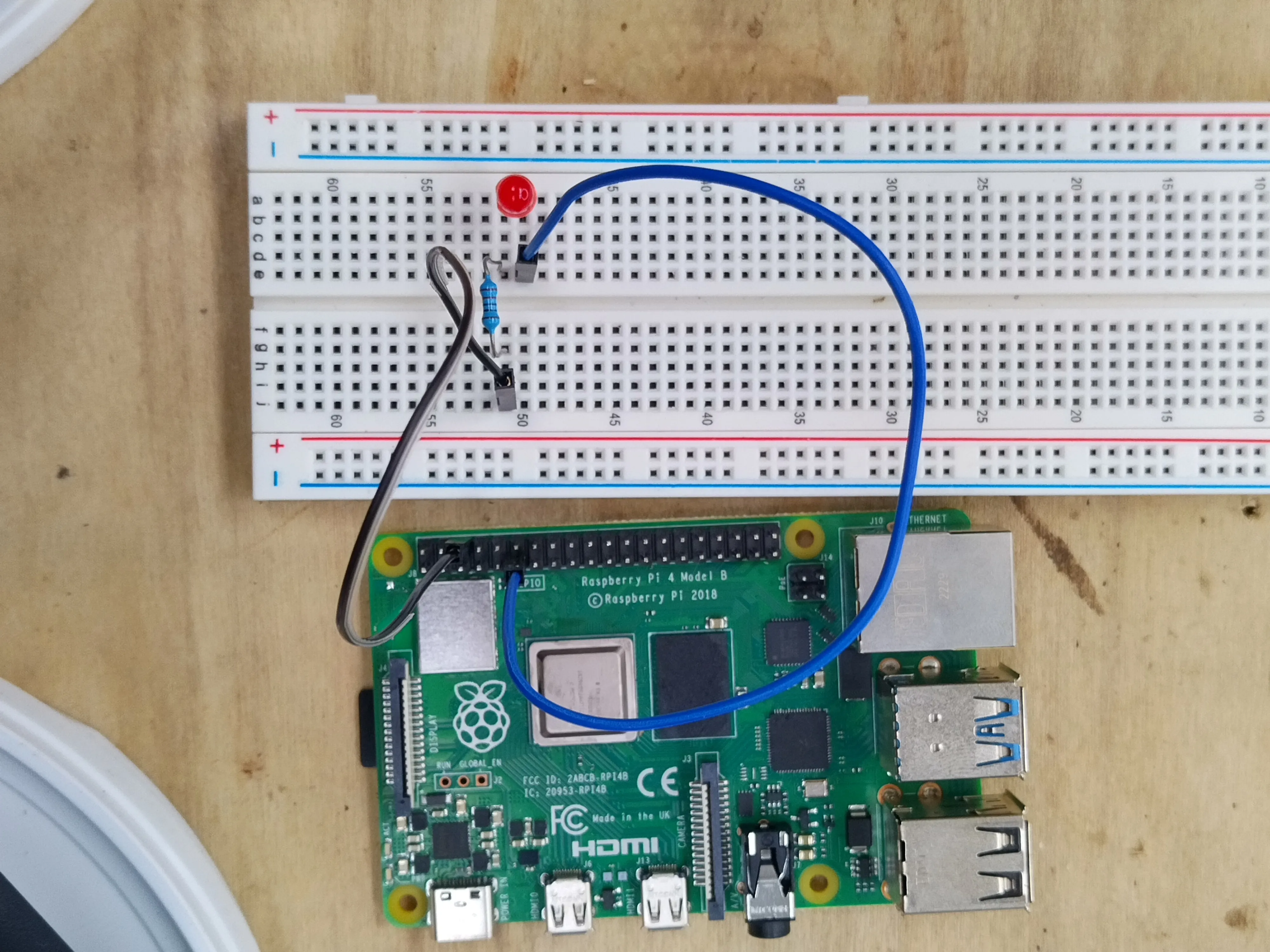
And the physical circuit looks like the following image, in which we’ve connected an M/F jumper wire from Pin 11 to the cathode of the LED. The anode of the LED is connected to the resistor, which is then connected to the ground pin through another M/F jumper wire.
The Code
Section titled “The Code”Changing Frequency
Section titled “Changing Frequency”Below is an example program to iterate over the entire range of frequencies available.
#include "splashkit.h"
int main(){    const int freqs[] = {10, 20, 40, 50, 80, 100, 160, 200, 250,                        320, 400, 500, 800, 1000, 1600, 2000, 4000, 8000 };    const int pwm_range = 255;    raspi_init();    gpio_pin led_pin = PIN_11;    raspi_set_mode(led_pin, GPIO_OUTPUT);
    raspi_set_pwm_range(led_pin, pwm_range);    raspi_set_pwm_dutycycle(led_pin, (pwm_range / 2));
    for(int i = 0; i < 18; i++)    {        write("At Frequency: ");        write_line(freqs[i]);        raspi_set_pwm_frequency(led_pin, freqs[i]);        delay(1000);    }
    raspi_cleanup();    return 0;}
Understanding the code
Section titled “Understanding the code”Lets break down this code and look at it in sections.
-
Initialise GPIO Hardware and values:
When using
pigpiod, we can actually set the sample rate for the daemon, which is a value determining how many times it can read a pin in a second. Each sample rate has a set of available frequencies, with the values defined in freqs array being the available frequencies for the default sample rate (more information can be found at Pigpio library -set_PWM_frequency).So, we define these values in an array and as a constant as these we don’t want them changing during the running of the program. We then define a standard range for our PWM, also as a constant, and then we do the usual initialisation of the Raspberry Pi Pins.
#include "splashkit.h"int main(){const int freqs[] = {10, 20, 40, 50, 80, 100, 160, 200, 250,320, 400, 500, 800, 1000, 1600, 2000, 4000, 8000 };const int pwm_range = 255;raspi_init();gpio_pin led_pin = PIN_11;raspi_set_mode(led_pin, GPIO_OUTPUT);raspi_set_pwm_range(led_pin, pwm_range);raspi_set_pwm_dutycycle(led_pin, (pwm_range / 2));for(int i = 0; i < 18; i++){write("At Frequency: ");write_line(freqs[i]);raspi_set_pwm_frequency(led_pin, freqs[i]);delay(1000);}raspi_cleanup();return 0;} -
Set PWM Range and Duty Cycle:
In this section we set the PWM range and duty cycles that we are using. We are setting the duty cycle to be half the PWM range, or in other words we’re setting it to 50%. We are not changing these values so we can specifically see the effects of changing frequency.
#include "splashkit.h"int main(){const int freqs[] = {10, 20, 40, 50, 80, 100, 160, 200, 250,320, 400, 500, 800, 1000, 1600, 2000, 4000, 8000 };const int pwm_range = 255;raspi_init();gpio_pin led_pin = PIN_11;raspi_set_mode(led_pin, GPIO_OUTPUT);raspi_set_pwm_range(led_pin, pwm_range);raspi_set_pwm_dutycycle(led_pin, (pwm_range / 2));for(int i = 0; i < 18; i++){write("At Frequency: ");write_line(freqs[i]);raspi_set_pwm_frequency(led_pin, freqs[i]);delay(1000);}raspi_cleanup();return 0;} -
Change the PWM Frequency:
This part is the main component of the code. We iterate over the previously defined frequencies and write where we’re at to the terminal. We then set the PWM to the particular frequency and wait for one second. This delay allows us to see the changes in the LED as the frequency increases. At the beginning there is a noticeable flicker, before the flickering stabilises to full illumination as the frequency increases.
#include "splashkit.h"int main(){const int freqs[] = {10, 20, 40, 50, 80, 100, 160, 200, 250,320, 400, 500, 800, 1000, 1600, 2000, 4000, 8000 };const int pwm_range = 255;raspi_init();gpio_pin led_pin = PIN_11;raspi_set_mode(led_pin, GPIO_OUTPUT);raspi_set_pwm_range(led_pin, pwm_range);raspi_set_pwm_dutycycle(led_pin, (pwm_range / 2));for(int i = 0; i < 18; i++){write("At Frequency: ");write_line(freqs[i]);raspi_set_pwm_frequency(led_pin, freqs[i]);delay(1000);}raspi_cleanup();return 0;} -
Clean Up Memory:
Finally we clean up and exit the program.
#include "splashkit.h"int main(){const int freqs[] = {10, 20, 40, 50, 80, 100, 160, 200, 250,320, 400, 500, 800, 1000, 1600, 2000, 4000, 8000 };const int pwm_range = 255;raspi_init();gpio_pin led_pin = PIN_11;raspi_set_mode(led_pin, GPIO_OUTPUT);raspi_set_pwm_range(led_pin, pwm_range);raspi_set_pwm_dutycycle(led_pin, (pwm_range / 2));for(int i = 0; i < 18; i++){write("At Frequency: ");write_line(freqs[i]);raspi_set_pwm_frequency(led_pin, freqs[i]);delay(1000);}raspi_cleanup();return 0;}
Build and run the code
Section titled “Build and run the code”We can build this program with the following command:
g++ pwm_frequency.cpp -l SplashKit -o pwm_frequencyWe can then run the program with the following command:
./pwm_frequencyChanging Duty Cycle
Section titled “Changing Duty Cycle”Below is an example program, very similar to the previous program, that demonstrates what the effect of modifying the duty cycle does to the LED.
#include "splashkit.h"
int main(){    const int pwm_range = 255;
    raspi_init();    pin led_pin = PIN_11;    raspi_set_mode(led_pin, GPIO_OUTPUT);
    raspi_set_pwm_frequency(led_pin, 1000);    raspi_set_pwm_range(led_pin, pwm_range);
    for(int i = 0; i <= pwm_range; i += 10)    {        write("At Duty Cycle: ");        write_line(i);        raspi_set_pwm_dutycycle(led_pin, i);        delay(1000);    }    for(int i = pwm_range; i >= 0; i -= 10)    {        write("At Duty Cycle: ");        write_line(i);        raspi_set_pwm_dutycycle(led_pin, i);        delay(1000);    }
    raspi_cleanup();    return 0;}
Understanding the code
Section titled “Understanding the code”Lets break down this code and look at the sections that are different.
-
Initialise GPIO Hardware and values:
Like before we set our PWM range to a constant value. We are using 255 as a general default, but it is important to know that the real range of PWM is dependant on the frequency that we set. More information can be found at Pigpio library -
set_pwm_range.#include "splashkit.h"int main(){const int pwm_range = 255;raspi_init();pin led_pin = PIN_11;raspi_set_mode(led_pin, GPIO_OUTPUT);raspi_set_pwm_frequency(led_pin, 1000);raspi_set_pwm_range(led_pin, pwm_range);for(int i = 0; i <= pwm_range; i += 10){write("At Duty Cycle: ");write_line(i);raspi_set_pwm_dutycycle(led_pin, i);delay(1000);}for(int i = pwm_range; i >= 0; i -= 10){write("At Duty Cycle: ");write_line(i);raspi_set_pwm_dutycycle(led_pin, i);delay(1000);}raspi_cleanup();return 0;} -
Set PWM Range and Duty Cycle:
When we set our frequency, we’re are using 1000Hz (which cycles at 1000 times per second). We then set our predefined PWM range, and if we refer back to the Pigpiod library we can see that a frequency of 1000 is the 14th available frequency at the default sample rate. This means that at this frequency we really have a range of 2500 and so our PWM range of 255 is valid.
#include "splashkit.h"int main(){const int pwm_range = 255;raspi_init();pin led_pin = PIN_11;raspi_set_mode(led_pin, GPIO_OUTPUT);raspi_set_pwm_frequency(led_pin, 1000);raspi_set_pwm_range(led_pin, pwm_range);for(int i = 0; i <= pwm_range; i += 10){write("At Duty Cycle: ");write_line(i);raspi_set_pwm_dutycycle(led_pin, i);delay(1000);}for(int i = pwm_range; i >= 0; i -= 10){write("At Duty Cycle: ");write_line(i);raspi_set_pwm_dutycycle(led_pin, i);delay(1000);}raspi_cleanup();return 0;} -
Change the PWM Duty Cycle:
In this section we have the main functionality of this program. We iterate over the range that we’ve set in increments of 10, and at each step we print out the duty cycle we’re currently on. We then set the duty cycle to this value and wait for a second so we can see the changes. We then reverse the loop and iterate back down to zero.
#include "splashkit.h"int main(){const int pwm_range = 255;raspi_init();pin led_pin = PIN_11;raspi_set_mode(led_pin, GPIO_OUTPUT);raspi_set_pwm_frequency(led_pin, 1000);raspi_set_pwm_range(led_pin, pwm_range);for(int i = 0; i <= pwm_range; i += 10){write("At Duty Cycle: ");write_line(i);raspi_set_pwm_dutycycle(led_pin, i);delay(1000);}for(int i = pwm_range; i >= 0; i -= 10){write("At Duty Cycle: ");write_line(i);raspi_set_pwm_dutycycle(led_pin, i);delay(1000);}raspi_cleanup();return 0;} -
Clean Up Memory:
Like usual, we clean up and exit the program.
#include "splashkit.h"int main(){const int pwm_range = 255;raspi_init();pin led_pin = PIN_11;raspi_set_mode(led_pin, GPIO_OUTPUT);raspi_set_pwm_frequency(led_pin, 1000);raspi_set_pwm_range(led_pin, pwm_range);for(int i = 0; i <= pwm_range; i += 10){write("At Duty Cycle: ");write_line(i);raspi_set_pwm_dutycycle(led_pin, i);delay(1000);}for(int i = pwm_range; i >= 0; i -= 10){write("At Duty Cycle: ");write_line(i);raspi_set_pwm_dutycycle(led_pin, i);delay(1000);}raspi_cleanup();return 0;}
Build and run the code
Section titled “Build and run the code”We can build this program with the following command:
g++ pwm_dutycycle.cpp -l SplashKit -o pwm_dutycycleWe can then run the program with the following command:
./pwm_dutycycleFurther Information
Section titled “Further Information”Changing PWM Range
Section titled “Changing PWM Range”As previously mentioned, when we increase the PWM range we increase the number of steps between the pin being always off and always on. We could change the range in the previous program and observe finer and more subtle adjustments occurring to the LED as the duty cycle increases. But this may be difficult to see when using a regular LED. A more effective demonstration of the capabilities of PWM would be through the use of an RGB LED, which can interpret analog-like signals achieved through PWM to mix red, green, and blue light in varying intensities. This allows for the creation of a wider spectrum of colours by adjusting the PWM range for each of the LED’s colour components.