
Reading Analog Signal
Learn to read analog signals with an Analog-to-Digital converter to connect a joystick to the Raspberry Pi
Written by: Jonathan Tynan
Last updated: Apr 27 2024
In previous tutorials we’ve covered reading and writing digital signals, and emulating analog signals through the use of Pulse-Width Modulation. In this tutorial we are reading analog signals with the MCP3008 analog-to-digital converter. While it’s relatively straightforward to emulate the sending of analog signals on the Raspberry Pi, to receive these signals requires additional hardware to do the conversions for us.
Components
Section titled “Components”-
Breadboard
-
Jumper Wires
-
KY-023 Joystick Module
This image shows a joystick module with two potentiometers and a push button. It features five pins: GND, +5V, VRx, VRy, and SW. VRx and VRy provide analog outputs for the X and Y axes, while SW is the digital output activated by pressing the joystick. GND serves as the ground connection, and +5V as the power supply. In this tutorial, we operate the module at 3.3V to ensure compatibility with the Raspberry Pi’s 3.3V data pins and prevent hardware damage.

-
MCP3008 Analog-Digital-Converter
This chip is the central component for reading analog signals. It has a side for device input and another for channel outputs. Below, we provide the pinout for this converter. In this tutorial, we guide you on how to select the reading channel and interpret the received data. Note the small semi-circle depression on the chip, shown in the picture, which indicates the correct orientation for installation. Proper orientation is crucial for successful operation.
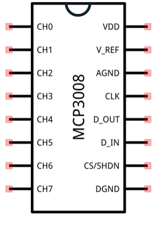
To connect this converter to the joystick we connect the VRx pin to CH0 and the VRy pin to CH1. It’s important that we connect the Raspberry Pi correctly, and the table below indicates which pins on the converter to connect to which pins on the Raspberry Pi.
MCP3008 Pin Raspbery Pi Pin VDD 3.3V V_REF 3.3V AGND GND CLK Pin 23 (SCLK) D_OUT Pin 21 (MISO) D_IN Pin 19 (MOSI) CS/SHDN Pin 24 (CE0) DGND GND To communicate with this device we must use SPI. SPI is a standard communication protocol in electronics and embedded devices. More information can be found at Serial Peripheral Interface.
The Circuit
Section titled “The Circuit”Below we can see the circuit diagram and photos for this project. We’ve connected the pins as described above, and the SW pin on the joystick is digital we can connect this directly to a pin on the Raspberry Pi, in this case we are using Pin 29.
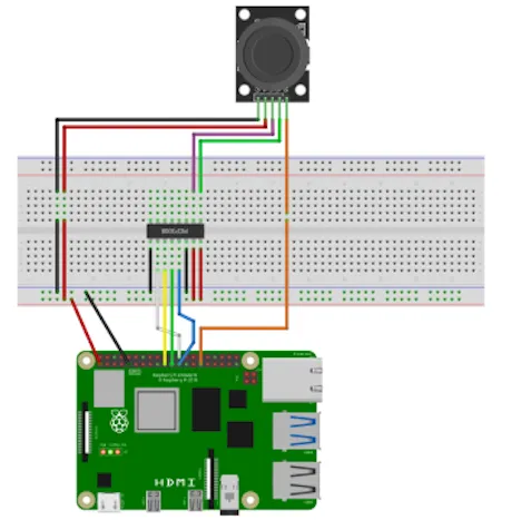
This circuit might look like the following image, reflecting our digital image above.

The Code
Section titled “The Code”We have a lot of complex looking code below, but as in previous tutorials lets break this down to analyse the program and how it works.
#include "splashkit.h"
using namespace std;
int read_adc(int spi_handle, int channel){    char send[3], recv[3];
    send[0] = 0b00000001;
    char ctrl_bits;    ctrl_bits = channel << 4;
    ctrl_bits = 0b10000000 | ctrl_bits;
    send[1] = ctrl_bits;    send[2] = 0b00000000;
    raspi_spi_transfer(spi_handle, send, recv, 3);
    int result = recv[1] << 8;    result = result | recv[2];    return result;}
int main(){    const int button_read_interval = 100;    unsigned long last_read = 0;
    const int axis_offset = 512;
    int num_presses = 0;    int x = 0, y = 0;
    raspi_init();    pins button_pin = PIN_29;    raspi_set_mode(button_pin, GPIO_INPUT);    raspi_set_pull_up_down(button_pin, PUD_UP);
    int spi_handle = raspi_spi_open(0, 1000000, 0);
    intervalTimer = create_time("read_interval");    start_timer(intervalTimer);
    open_window("dummy_window", 1, 1);    while(!any_key_pressed())    {        process_events();        unsigned long curr_time = timer_ticks(intervalTimer);
        if(curr_time - last_read > button_read_interval)        {            last_read = curr_time;
            if(raspi_read(button_pin) == GPIO_LOW)            {            num_presses++;            }        }
        x = read_adc(spi_handle, 0) - axis_offset;        y = read_adc(spi_handle, 1) - axis_offset;
        write("\033[2J\033[H");        write("X: ");        write(x);        write(" Y: ")        write_line(y);        write("Button Presses: ");        write_line(num_presses);
    }
    close_all_windows();    free_all_timers();    raspi_spi_close(spi_handle);    raspi_cleanup();    return 0;}
In this code we’ve got our main() function that drives the entire program, and we have the core component of this code - the read_adc() function.
Lets look at this later on, and begin by breaking down main().
main() code - Break down
Section titled “main() code - Break down”-
const int button_read_interval = 100;unsigned long last_read = 0;const int axis_offset = 512;int num_presses = 0;int x = 0, y = 0;
To start, we set the interval for button reads and store the last read time in last_read. We also define an offset for the joystick axes. This offset is necessary because the joystick’s output ranges from 0 to 1023, with a neutral position output of 512. By subtracting this offset, we can determine both the magnitude and direction of the joystick’s movement. For instance, a value of -512 indicates full movement in one direction, while +512 indicates the opposite.
-
raspi_init();pins button_pin = PIN_29;raspi_set_mode(button_pin, GPIO_INPUT);raspi_set_pull_up_down(button_pin, PUD_UP);
Next, we configure the GPIO pins as usual. While we typically use PUD_DOWN to detect when the button pin is GPIO_HIGH, I’ve switched to PUD_UP for this tutorial to detect GPIO_LOW instead. This change was necessary due to the specific configuration of my joystick module, which might differ between manufacturers. This setup was determined through experimentation. If you encounter issues with button press detection on your joystick, experiment with setting or disabling different resistors on the button pin.
-
int spi_handle = raspi_spi_open(0, 1000000);
We initiate communication with our converter by calling
raspi_spi_open()with two parameters, storing the return value in spi_handle. This value references the SPI connection and a negative value indicates an error. The first parameter specifies the device channel, we set it to zero as we use theCE0pin (pin 24) on theCS/SHDNline, thoughCE1pin (pin 26) can also be used with a value of one. The second parameter defines the SPI communication speed, set at 1,000,000 bits per second, adjustable between 32,000, and 32,000,000 bits per second. -
intervalTimer = create_time("read_interval");start_timer(intervalTimer);
We create a timer and start it so we can correctly debounce our button presses.
-
while(!any_key_pressed()){process_events();...}
As we’ve done in previous tutorials we run this code while no key has been pressed, and we process events at the start of the loop.
-
unsigned long curr_time = timer_ticks(intervalTimer);if(curr_time - last_read > button_read_interval){last_read = curr_time;if(raspi_read(button_pin) == GPIO_LOW){num_presses++;}}
In this section we’re just detecting if the button has been pressed and incrementing the
num_pressesvariable if this is the case. -
x = read_adc(spi_handle, 0) - axis_offset;y = read_adc(spi_handle, 1) - axis_offset;write("\033[2J\033[H");write("X: ");write(x);write(" Y: ")write_line(y);write("Button Presses: ");write_line(num_presses);
Then we read the values of the joystick position from our converter, apply our offset, clear the terminal, and finally we’ll print out our joystick information.
-
close_all_windows();free_all_timers();raspi_spi_close(spi_handle);raspi_cleanup();return 0;
Once we exit this program we do the usual cleanup of the program, except must close the SPI connection that we’ve opened and used. We do this with the
raspi_spi_close()and give it the handle that references this connection,spi_handle.
read_adc() code - Break down
Section titled “read_adc() code - Break down”Okay, now lets have a look at the read_adc() function.
-
char send[3], recv[3];send[0] = 0b00000001;
To transfer data between our device and the converter, we create send (
send) and receive (recv) buffers, each sized to three bytes. This aligns with the data transfer needs of the MCP3008 chip. The first byte of the send buffer is set to 0b00000001, initiating a start bit that signals the converter to begin transmitting data back to us. For more details, refer to MCP Datasheet. -
char ctrl_bits;ctrl_bits = channel << 4;ctrl_bits = 0b10000000 | ctrl_bits;send[1] = ctrl_bits;send[2] = 0b00000000;
To configure the converter, we send a second byte containing control bits that specify the operating mode and the input channel. The format is
0bXYYYZZZZ:Xselects the mode (1 for single, 0 for differential—we use 1 for single mode)YYYrepresents the input channel in binaryZZZZare ‘don’t care’ bits that are ignored.
For manipulation, we use bit-wise operations. We prepare the control bits in the following way:
char ctrl_bits;ctrl_bits = channel << 4;We first shift the bits of the channel number left by 4 and position it in the Y positions described above. This is a bit-wise operation and to demonstrate, lets say
channelis equal to 5 or0b00000101when we bit-shift we literally move each bit a number of spaces in a direction so we bit-shift left by 4 and this results in0b01010000.ctrl_bits = 0b10000000 | ctrl_bits;We then set the mode by performing an OR operation with the mode bit set to 1. If we following the previous example,
ctrl_bitswould now hold0b11010000. The third byte isn’t used so we just set it to 0. For more details, refer to MCP Datasheet. -
raspi_spi_transfer(spi_handle, send, recv, 3);int result = recv[1] << 8;result = result | recv[2];return result;
Finally, we transfer the data using
raspi_spi_transfer(). We pass ourspi_handle,sendandrecvbuffers, and specify three bytes for the transfer. Post-transfer, recv holds the converter’s output. As detailed in the MCP datasheet, the converter returns a 10-bit number split between the second and third bytes of the buffer.To decode this, we shift the second byte (recv[1]) left by 8 bits to align the data, and then merge it with the third byte (recv[2]) using a bitwise OR operation. The combined result is returned as an integer. For more details, refer to MCP Datasheet.
Now that we’ve covered the entirety of this program, run it like we’ve been doing previously and your output should look something like this:
Further Information
Section titled “Further Information”MCP Datasheet
Section titled “MCP Datasheet”In this tutorial we have done some fairly advanced stuff. We’ve set control bits to command the converter, and we’ve extracted values from memory buffers. But how do we know what to set or extract and where?
This information comes from the datasheet for a particular device. If we have a look at the MCP3008 Datasheet we are able to find a huge amount of technical information, and graphs and diagrams about this chip. Most of this information we can safely ignore, but the relevant information we need appears on page 19 and page 21.

On page 19 there’s a table that tells us what control bits we must set for specific configuration. This table is provided above. If we then look at page 21 we are able to see a graph describing the transmission of data to and from the chip. If we look at the bottom section, reproduced below, we can see exactly what bits we must set, and what bits contain the received data.
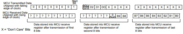
This section first describes the transmitted data, and splits into bytes. We can see the start bit in the first byte, and the four control bits we’ve set in the second byte. It then describes the received data, and we can see that the start of the 10-bits of received data is at position 6 (B9), with the rest of the bits stored in the subsequent positions.